HOW TO REPAIR A 1947 GEAR : Most of the time a machine shop will get a shaft to duplicate or some sort of mechanism to repair that is very straight forward.
But what happens when your customer calls with something more challenging?
During normal maintenance this gear was found to be damaged. We were called to repair the gear. Here’s what we were presented with.

The gear is 24” in diameter, cast iron and a worm gear. The damage was a crack from the keyway, through the hub and web of the gear. Notice the crack leading from the keyway and through the hub and web:

On the opposite side you can see more of the crack through the keyway, hub and web:
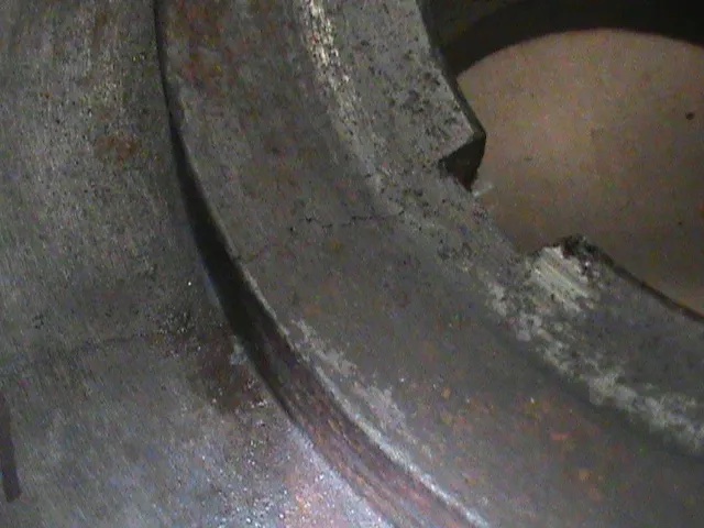
It’s a little hard to see but the crack runs in two directions from the hub through the web:

In the next picture you’ll see what makes this gear special and one of the reasons it is not a good candidate for replacement.
Note the date of manufacture:

September 1947.
Old isn’t necessarily equal to obsolete. Many older machines are still in service doing very profitable work. We refurbished and added controls to a large roll grinder (28” swing x 144”c-c x 18000 lbs.) that had originally been manufactured for US Steel in 1928. That machine is still in use today.
The machine is Italian. It is a bottle filling machine. Replacement parts are non-existent. Documenting the gear and producing a replacement would be prohibitively expensive.
However, even after all these years, the machine is a workhorse. It is robustly built, expensive to replace and therefore worthy of repair. Besides those reasons there were additional reasons that we recommended repairing the gear and why we chose our method of repair.
First we noted that the gear tooth form was in excellent condition.

Even after more than seventy years of service the gear showed nearly no wear at all. This indicated that the machine required very little torque to turn and do its job. Therefore gear tooth loading is very low yielding little or no gear tooth wear. This also told us that there was very low loading on the keyway and hub parts of the gear.
Next, using a dial bore gauge, Tyler, one of our engineers, profiled the gear bore to determine its condition. The bore turned out to be not the best but also importantly did not show any sign of wear from use.
Remembering that the gear was manufactured in Italy in 1947, a country recovering from a devastating war and undoubtedly short on resources, it is possible that the gear bore is in the same condition as when it was new.
To make sure, Tyler traveled to the customer’s plant to profile the machine’s shaft and inspect its condition. The shaft turned out to be in excellent condition with no wear visible and the shaft keyway in nearly new condition.
This was a further indication that the machine required little torque to run.
If the gear had shown excessive wear from high loading but the rest of the machine was worth saving then the appropriate path would be to document the gear, produce an accurate model and detail drawing by which we would manufacture a replacement gear. While an expensive choice sometimes this gives the best value.
However, having determined that both the machine and gear are worth repairing the next step was to decide how to repair the gear. The gear still needed to be modeled but modeling and specifying the gear teeth could be omitted as they were not incident to the needed repairs.
We were only interested in the overall geometry of the gear and specifically the hub and web section. This area needed to be accurate to facilitate the design of the repair. We could then produce shop drawings detailing the needed modifications to the gear and the fabricated parts required for the repair.
Ideally if the hub and web section of the gear had more material we could bore out the entire hub and insert a new hub. That could be attached to the remaining web by bolts and pins. However, the central section of this gear is fairly light in its design. There is not enough material available to support a fully shaped replacement hub.
Therefore remembering that the gear is lightly loaded and that in all probability the cracks we see developed early in the gears life we could be comfortable with a less aggressive repair.
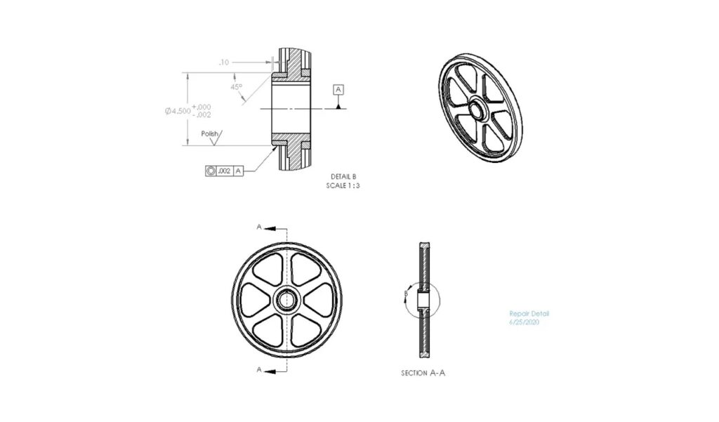
Fortunately the hub has sufficient material and therefore on the seal side (the side with the date stamp) and the opposite side we can machine the hub. Then, using 4140 steel, we can fabricate rings that can be shrink fitted to both the sides of the gear.
On the seal side the repair ring can then be machined to the seal manufactures specifications for size, concentricity and finish. The opposite side needs only to be faced to the correct height to position the center of the gear teeth to the driving worm.
The drawing below is typical of drawings produced to guide the shop through the repair process. This drawing shows the finish details for the seal side of the gear.
Once the gear was machined and the two fabricated rings fitted to the gear we were able to get an indication that this repair was going well. The photo below shows oil being forced out of the cracks that we saw in an earlier photo.

This is caused by the repair ring tightening on the parent hub as the ring cools. As the ring tightens it causes the cracks to close forcing out small amounts of oil that have collected in the undisturbed, open crack. This is a good sign.
The next photo will give you a better idea of the size of the gear.

I mentioned older machines. The lathe in this photo was manufactured in Los Angles in 1952. It is as accurate today as when new. We use it almost every day.
Here the “seal side” of the gear is being “indicated in” before machining. This is to insure that the gear is running true to the gear bore. After this the ring is machined according to the drawing shown above.
The gear is now repaired and ready to get back into service. Notice that the crack and the date stamp we saw are still visible. However, now the crack has been compressed by the repair rings and also the hub is supported on both sides of the gear by the rings.

By understanding the function of the filler machine and the forces that the gear is subjected to were able to design a repair plan that suited the needs of the machine and gear. This requires engineering expertise as well as an experienced machining facility. There are many such facilities across our country. We are one of them.
Thanks for taking the time to read this presentation. If you should have a question or comment about this article or have a problem you think we might be able to help with, send us a message. We are happy to talk with you.